

This project is part of my Arduino Pinball adventure where I’m learning Arduino programming while having fun building parts for a pinball game. The pinball targets in this projects is what you would call “drop targets” in traditional pinball games. The ball knocks out targets one by one to get score and eventually a bonus when all targets are down.
 In this post I will explain in detail how I have made the targets and how the Arduino code works. I’m experimenting a lot with different types of electronics and not necessarily building what would be a “traditional” pinball game. My goal is simply to make a fun, functional and good looking pinball game using Arduino.
How it works – target gameplay
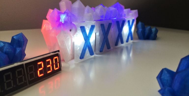
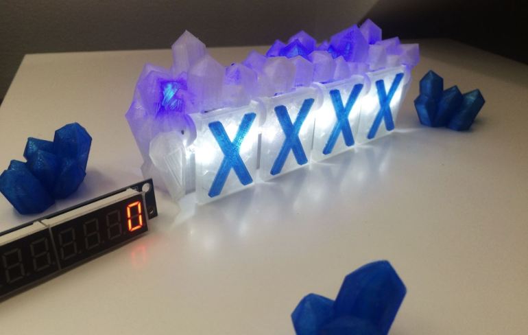
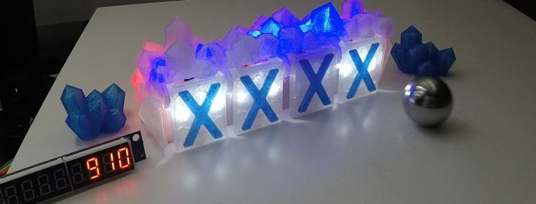
The design of the targets – the glowing crystals – are part of my game theme where you “collect crystals” to get points. The crystals have a blue glowing effect as default. There are 4 targets. When a target is hit the crystals flash in red-orange to indicate mining or blasting. When the pinball hits a target 5 points are added to the score and the target light goes out. When all 4 targets are hit a bonus of 200 point are added and all the targets flashes and resets to “on”. After a target is hit and the light goes out you can still hit it and get 5 points. I think this will keep the game play interesting, but this may change as the complete pinball game evolves.
Designing the targets
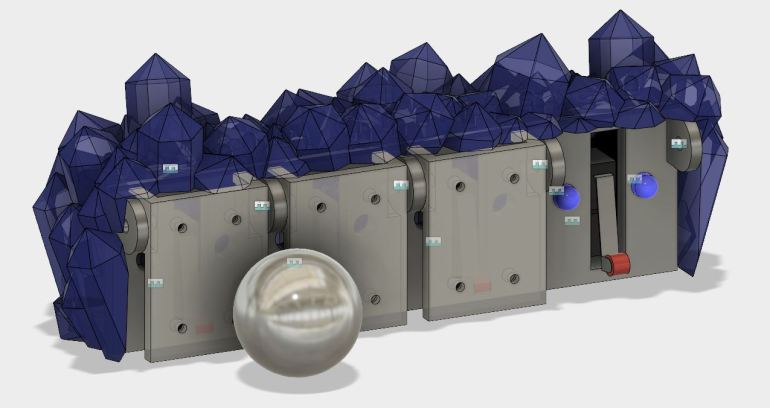
I have made 4 targets in a crystal formation that I have modeled in Autodesk Fusion 360 and 3D printed. The idea is based on a project I started on last year that just ended on a breadboard, but that I thought could be expanded more.
Bill of materials
Most of the electronic parts and mounting hardware I have bought from ebay. A quick search for the items gives lots of results. I have uploaded the 3D models on thingiverse.com for anyone to download.
- 3D printed parts (link to parts on thingiverse.com)
- A crystal
- A bracket
- 4 target plates
- 4 X shapes or other symbol
- Arduino microcontroller
- Display MAX7219
- 1x 2mm steel rod for the target plate mounting. I used two separate ones I had.
- 4x microswitches
- 4x 10k Ohm resistors
- 3x 5mm RGB LED
- 10x 3mm blue LED
- 1x 150 Ohm resistors for each blue led and 3 for each RGB
- 8x 5mm white LED
- 4x 56 Ohm resistors
- 8x M2 10mm bolts (for the microswitches) / M2.5 can also be used
- 8x M2 nuts (for the microswitches) / M2.5 can also be used
- 2x M3 brass threaded inserts
- 2x M3 6mm bolts
- small wood screws or other mounting screws for the bracket
Note; always check the specification on LEDs and use the appropriate resistors.
Electronics and wiring
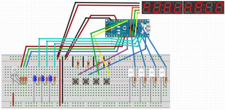
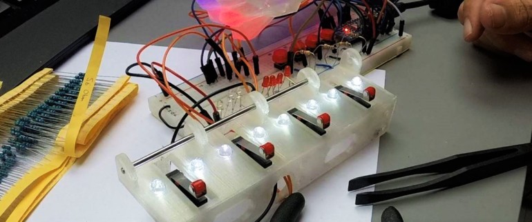
I first built the circuit on a breadboard to understand how I could control the LEDs and functionality. I simplified it using just the minimum parts needed to see the effects and functions. I used this breadboard setup throughout the build process for testing as I needed to see that switches and LEDs functioned as intended.
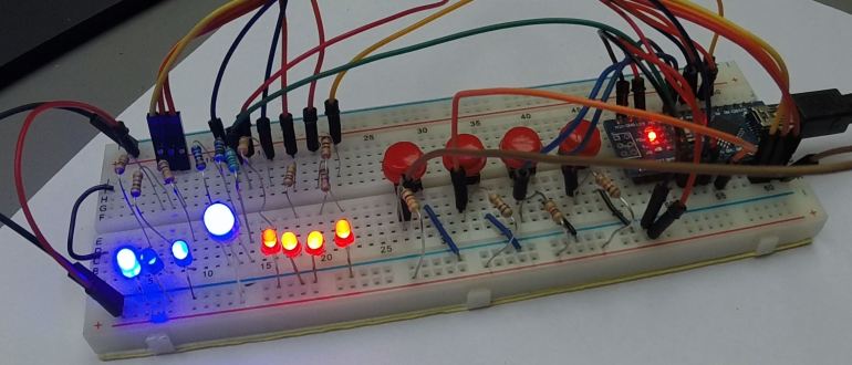
- The three small blue LEDs are pulse fading and will make the crystal part glow and twinkle. In the crystal I’ll add several LEDs to the same pin to spread out the light effect.
- The big blue LED is the RGB LED. It’s pulse fading in blue as default but changes to red-orange when a target is hit. I’ll use three of these in the crystal.
- The four red LEDs are for each target and will be changed for two white LEDs for each target.
- The four red switches are the targets. Pressing a switch is the same as hitting a target.
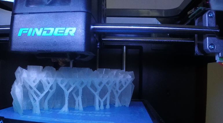
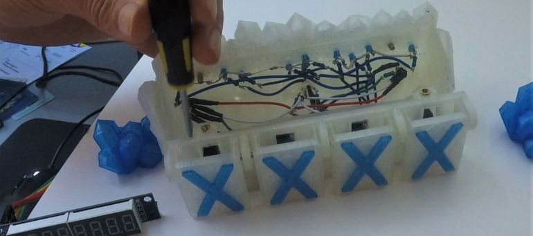
When I had the 3D printed parts ready I started placing blue LEDs in the crystal shape. I used more than what I had on the breadboard because I wanted to spread out the puls fade color effect through the whole part. I soldered the LEDs together with the corresponding resistors and added some longer wires I could connect to a breadboard for testing later.


In the crystal I also added 3 RGB leds. These will have the default blue color fade effect, as well as the red-orange color effect when a target is hit.
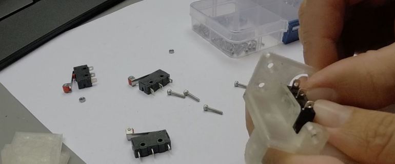
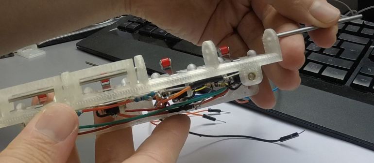
Next I added the four micro switches and soldered on wires and resistors.
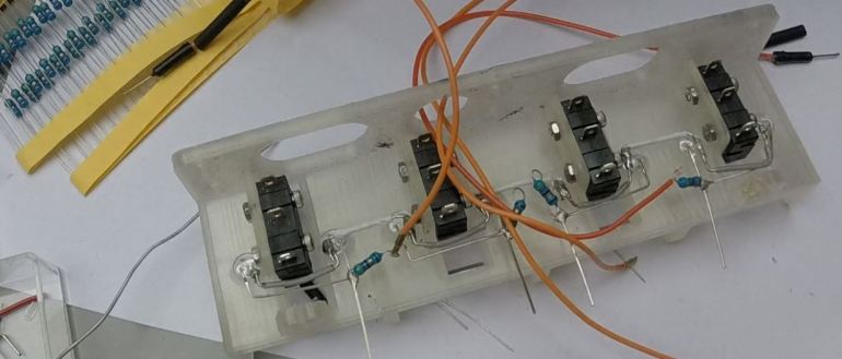
When the switches was mounted and adjusted into position I tested all functionality using the breadboard I had already set up. I could then swop each of the pins and see how things worked. I had to solder many of the connections twice the loose cables broke off.
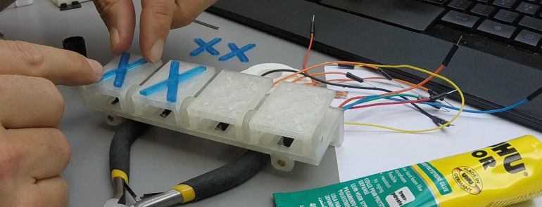
I printed the X shapes in blue PLA and glued them onto the targets. This is good enough for testing how this assembly work, but the target plates needs to be redesigned to be able to take the 27mm steel ball punch without falling apart.
Another thing I have noticed is that with sufficient force, the target plate will push the entire micro switch back as there are some wiggle room for the small M2 screws, resulting in the target plate getting stuck.
The target plates are currently designed so that they can’t swing out because of a bumper in the top, but there should also be a bumper shape in the bottom to avoid too much force on the micro switch.
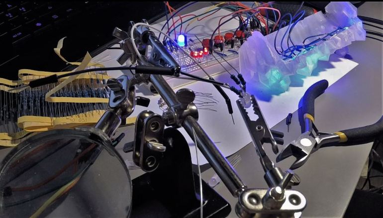
I mounted the target bracket on a white board to test it with a 27mm pinball. I drilled holes in the board according to the holes in the target bracket and mounted it with wood screws. I made bigger holes for the cables to go through. Since this is a prototype and I’m only testing it I’m placing a small breadboard with an Arduino Nano on the backside of the board. Next I mounted the crystal shape on top of the bracket with M3 bolts. Threaded inserts are inserted with heat, I used the soldering iron to push them in.
The finished Arduino pinball targets
The Arduino code
The Arduino sketch is available on Github.com for download. Suggestions and improvements is always welcome!
Lessons learned
- Electronics
- Designing parts so that electronics can be soldered directly into the parts is not recommended, but sometimes the only way. The next time I design a mechanical part that will be assembled with electronics I will try to make space for a separate PCB for the electronics. The PCB can then be bolted into the assembly, with LEDs and switches soldered securely.
- Use connectors instead of long loose cables. Cables moving will break off where they are soldered.
- More focus on RGB LED- how to control several with less pins on the Arduino. It might be better in this project to use only RGB LEDs, to have complete control of colors and effects.
- The MAX7219 display behaves strangely. Sometimes it’s on, sometimes it’s not. It goes into 8888888 after a short while. A new display is in the mail, but the code should be checked and revisedtoo.
- Mechanics
- When 3D modeling, also add as much electronic components as possible. Especially cables and wires. This will make it easier to understand where more space is needed
- When designing for 27mm steel pinball, make it rugged. Direct forces away from the electronics.
- The 2mm steel rod used for the target plates works great. For moving parts, plastic against plastic should be avoided. PLA for 3D printing does not work for moving parts, always use steel rods, metal bearings etc.
- Software & Code
- Still stuff to improve. Need to work more on arrays.
- The “struct” code was interesting (used for the 3 blue LEDs)
Thanks for your interest in the Arduino project!
If you have read all the way down here – hope you enjoyed this project! Please use the like button to tell me this was an interesting read 🙂 🙂

I couldn’t get your code to compile, perhaps think about putting a link for it on the page,thanks
LikeLike
Thanks for the feedback! I haven’t found a good way to post code on this web system. I’ll look for a better way to share code.
Update 23. may 2017: The arduino code is now on github.com
LikeLike
Monta o conjunto sob encomenda e vende pela Internet.
LikeLike
Congratulations, thanks for the ideas.
LikeLiked by 1 person